Let us make a short scenario. The player should walk from point A to B, where he answers some dialog and then to point C. He is not allowed to enter some restricted area, if he does so, he fails the scenario. He can also use the map and see his position as well as the position of the restricted area.
Such scenario has three acts: act "going to B", act "dialog shown"
and act "going to C". The position of point A, B and C and the
restricted area will be written in file
map.xml.
You should be already familiar with configuration file, so go and alter the configuration file. It should look as this:
<?xml version="1.0" encoding="UTF-8"?>

<!-- Here you can specify the language of the scenario. -->
<scenario lang="english">

	<!-- Set the minimal number of players that can perform the scenario (usually 1). -->
	<players min="1"/>

	<!-- The list of DSLR rule files using the specified DSL. You have to specify the paths. -->
	<rules dsl="edu-english.dsl">
		<package src="MyRulesFile.dslr"/>
	</rules>

	<!-- The structure of acts -->
	<scenes>
		<act id="parts">
			<act id="going to B"></act>
			<act id="dialog shown"></act>
			<act id="going to C"></act>
		</act>
	</scenes>

	<!-- List of map files -->
	<maps>
		<map src="map.xml"/>
	</maps>

</scenario>
Now we have to describe such scenario in rules.
In previous tutorial we have created a project with
MyRulesFile.dslr. Now you have to understand its
contents and learn how to write scripts for your own scenarios.
For your comfort can be all commands and conditions formulated in simple bare sentences. This is called DSL - Domain Specific Language. These senetences are translated into Drools and Java commands.
The rule package consists of two parts: head and rules. In the head there are four important objects
-
Package declaration: Namespace of these rules. For you it has no deep sense, just use unique name.
package mypackage; -
Imports declaration: This declares the classes that will be used in the rules. Because you use DSL in all the rules you do not have to add any imports, just use the two from ExampleScenario.
import cz.cuni.amis.pogamut.edu.Scenario.State; import cz.cuni.amis.pogamut.edu.controlserver.KeyEvent.Event; -
Globals declaration: Variables that are accessible in all rules. As for the imports, you will not use them directly, only through DSL. That is why you must declare only one global variable:
global cz.cuni.amis.pogamut.edu.ut2004.UT2004Scenario scenario -
Expander declaration: You can think about expander file as a dictionary where are all translations of commands and conditions in DSL. You should alter the expander to the path to your DSL file.
expander edu-english.dsl
The second part contains the rules. All of these have the form:
rule "unique rule name"modifierswhenconditionsthencommandsend
Every 100 miliseconds are these rules tested; if are the
conditions in LHS (left-hand section, the part of
the rule between when and then
keywords) for some rule satisfied the rule is going to be fired. This
means that the commands in the RHS (right-hand
section, the part of the rule between then and
end keywords) are executed. The commands could
change the situation and another rule can be fired. In one moment can
the conditions of multiple rules be satisfied - all of them are fired
then.
The LHS can contain multiple conditions, each condition on
single row. The default meaning of this that all of the conditions
must be satisfied at one moment to fire the rule. There is a default
and relation between them. There is also a way how
to say that only one condition from some of them must be satisfied.
This is the or relation. You can write it this
way:
when
    condition 1
    or
    condition 2

then
If you want to write more complex LHS, use parentheses:
when
    condition 1
    (condition 2
    or
    condition 3)
    condition 4
then
This means that the both condition 1
and condition 4 must be satisfied and also
either condition 2 or
condition 3 (or both of them). The order of
conditions is not vital but it affects the performance. You should put
the more computionaly difficult conditions on the bottom and the
bottleneck conditions on the top. If you do not know which order is
better, do not care.
See documentaion for the complete list of currently supported conditions.
Unlike in the LHS, the order of commands in RHS is very important. Each command must be written in a single row and these are executed in a top-down order. The complete list of currently supported commands is in documentation.
Modifiers alter the way how the rules are executed. For the complete list look into the Drools documentation but for you can be important these two:
-
saliencenumber: This modifier determines the order of rules in which they should be fired. The default salience is 0. If the LHSs of multiple rules are satisfied at one moment the first rule which is executed is the one with the highest salience and so forth. -
no-loop: When the RHS of rule is executed it could modify the objects that the conditions are testing. This would result in another firing of this rule. This modifier prohibits such behaviour. Nevertheless, when such modification fires second rule, its commands can modify the conditions for this (first) rule and it can fire again. Theno-loopmodifier does not prevent such behaviour.
If you want to write your own comments (what is strongly
recommended) or remove some condition or command for debugging
purposes (you want to add it again in the future), start the line with
sharp character #. Everything between the sharp and
the end of line is considered as comment and Drools ignore it.
For debugging purposes we put some "log" commands into the rules. These have no impact on the scenario but we will see its proceeding.
Let us look on the MyRulesFile.dslr:
package com.example.myscenario

import cz.cuni.amis.pogamut.edu.Scenario.State;
import cz.cuni.amis.pogamut.edu.controlserver.KeyEvent.Event;

global cz.cuni.amis.pogamut.edu.ut2004.UT2004Scenario scenario

expander edu-english.dsl
From your point of view there is nothing interesting here. This part will me always the same, only the package name will change. The actual action of the scenario is described below:
rule "Scenario start"
    when
        scenario is ready
    then
        log "Starting the scenario"
        start scenario
        transport player "Player1" to "point A"
        enable current position on map
        perform act "going to B"
end

rule "Arrival to B"
    when
        performing act "going to B"
        player is nearby "point B"
    then
        log "Arrived to B"
        show message "You have arrived to poing B" for 10 seconds
        perform act "showing dialog"
        # begin of the definition of the dialog
        create dialog "myDialog"
        create option list "options"
        add "options" to dialog "my dialog"
        add new option "Option A" to "options" as "1"
        add new option "Option B" to "options" as "2"
        add new option "Option C" to "options" as "3"
        create submit button "submit"
        set size of "options" to 0.9, 0.7
        set position of "options" to 0.05, 0.1
        set text on "submit" to "Submit"
        set size of "submit" to 0.4, 0.1
        set position of "submit" to 0.3, 0.8
        add "submit" to dialog "my dialog"
        # end of dialog
        show dialog "in shop"
end

rule "Dialog returned 1"
    when
        performing act "showing dialog"
        dialog "myDialog" returned in "options" value "1"
    then
        log "option A"
        show message "You have selected option A" for 10 seconds
        perform act "going to C"
end

rule "Dialog returned 2 or 3"
    when
        performing act "showing dialog"
        (dialog "myDialog" returned in "options" value "2"
            or
         dialog "myDialog" returned in "options" value "3")
    then
        log "option B or C"
        show message "You have selected option B or C" for 10 seconds
        perform act "going to C"
end

rule "Arrival to C"
    when
        performing act "going to C"
        player is nearby "point C"
    then
        log "Arrived to C"
        show message "You have succesfully finished the scenario"
        finish scenario
end
This is the description of the scenario. Although the definition of the dialog looks awfully, there is nothing difficult about that. There is a main dialog with two elements: option list "options" and submit button. The option list contains three options with their particular values. All the other commands specify the shape and positioning of the two mentioned elements. That is all.
We have not covered two events: when the player wants to display or hide the map and when he enters the restricted area. The first one would look as this:
rule "Map showing"
    when
        user pressed "M" key
        map is hidden
    then
        set keypress "M" processed
        show map
end

rule "Map hiding"
    when
        user pressed "M" key
        map is shown
    then
        set keypress "M" processed
        hide map
end
Unfortunately you have to manually discard the keypresses - if you would not do that, the second condition would fire (and hide/show the dialog again) causing an infinite loop of showing and hiding. The automatic discard of the keypress would not be wise in case that two rules would be waiting for the keypress.
Thanks to the map files (we will show how to make them in the next section) is the intrusion into the restricted area very simple to intercept - we need only single simple rule:
rule "Restricted area"
    when
        player is in area "restricted"
    then
        log "Entered restricted"
        show message "You have entered the restricted area! You have failed the scenario."
        finish scenario
end
Voila, all rules for your scenario are completed.
It would be very uncomfortable to use commands as "if the player is in rectangle specified by coordinates 324, 5654, 756, 6544" and such. That is why all these coordinates are stored in a file called map file. More accurately, there can be more of such files but the information from them are merged during the loading.
The parts of space are called areas. There are two basic types of them: simple areas and complex areas. The simple areas are rectangles, circles and polygons and you usually do not assign a name (ID) to them. The complex areas do not have coordinates - they are specified by their subareas. These subareas can be also complex areas or simple ones. They form a tree-like structure: simple areas form streets, squares, parks and such, these form districts and districts form a city. This partitioning is up to you - nothing forces to have three levels, you can have two or fifty of them.
Sometimes you would like to have some point marked on the map or refer to the point in the scenario. These are called POIs - points of interest. You can also set their symbol, color and description.
Similar to marks are paths. These are broken lines displayed in the map. You can set their color and width. Unlike the POIs you cannot refer to them in rules because they have not a single position.
You do not have to edit the map manually, there is an editor provided, of course.
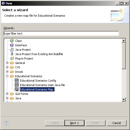
ES provides a wizard to easy map file creation. Right-click on the folder where you want to create the map file and select -> . In the dialog select from the folder and press the button.
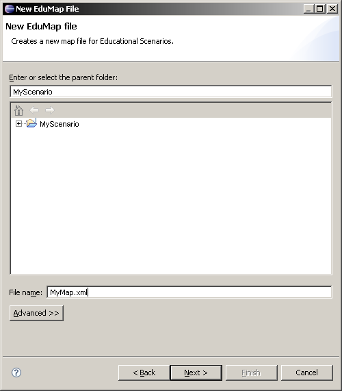
Fill in the new name of the map file with .xml extension (e.g.
) and press button
again.map.xml
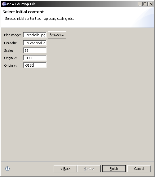
Select the initial content. The entries have following meaning:
-
Plan image is the image displayed on background when you edit the map file.
-
UnrealID is the UT2004 identifier of the image. When displaying in game (e.g. as in the map dialog) the image is not loaded from the filesystem (from the location stored in the Plan image) but it is stored as a texture in
UT2004/Textures/TextureFile -
Scale determines the ratio between one pixel on the plan image and one UT2004 unit. It is 32 for the unrealville.png.
-
Origin X and Origin Y are the UT2004 coordinates of the left top corner of the map. For UnrealVilleBig map are these -8900 and -3150.
Press the button when all the data are filled.
Now should your new map file appear in the package tree view
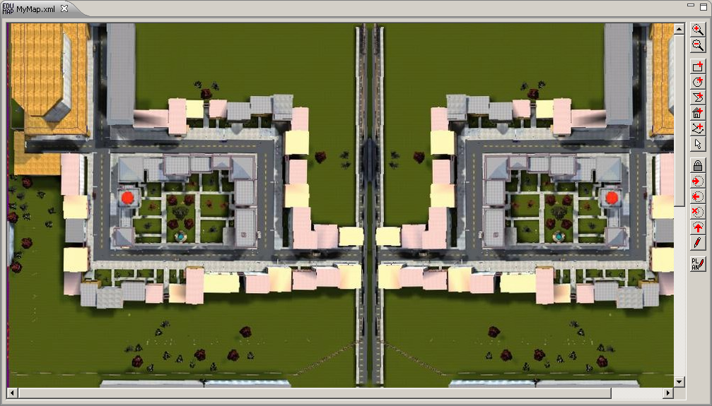
After you have created the map file the editor should automatically open. The screen will look as this:
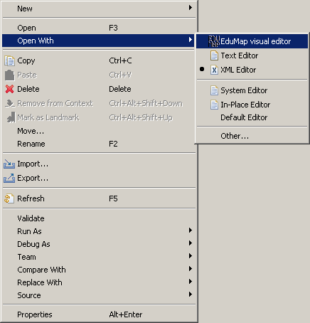
If you close the editor you can open it again by on the file and selecting -> as you can see on the image below. should do the same job when you try to open it for the second time.
-
As the first step you'll select the points A, B and C. Select the (sixth button from top, the one with house icon) and left click on some street in the map. A dialog will appear where you should enter the id
"point A"and name, symbol and its color displayed in the map. Do the same thing also for other two points. -
We have to create the restricted area. It could be just a simple rectangle, but we will make it a little more complex to learn how to use map editor. Select (third button from top) and mouse over some area - a rectangle will appear there. Then select (fourth button), press somewhere near to the rectangle's edge and drag to set the circle's perimeter.
-
Now should be the circle selected (it should have blue filling). If it is not, use (eighth button from top) and click inside the circle to select it. Now we will create the complex area containing both the circle and the rectangle: press button (third from bottom). The circle has no superior are yet - a dialog will appear where you should enter type e.g.
zone(this value is not important now) and idrestricted. This id is the name we have used in the rule "Restricted area". The circle should be filled with green now indicating that a complex area containing this area is selected. -
The new complex area currently contains only the circle but we want it to contain both the circle and rectangle. Lock the selection of the complex area with button (seventh from bottom). The circle should became yellow. Now use the to select the rectangle. Press the button. Nothing seems to happen but when you outside the areas, the rectangle will became also yellow.
-
We have not tested the (fifth button from top) yet. Use it to create an area intersecting with our restricted area. Then press the button (fourth from bottom). After outside you will see that the polygon is orange - the polygon's space is not a part of the complex area.
-
To see things clearly press the button, select the rectangle and then press the . You can see the hierarchy clearly now.
-
Areas are not visible in the in-game map. If you want to stress them use the (seventh from top). Although the path tool does not allow to create closed cycles, you can put the last point nearby to the first to make such effect.
-
Save the map, we are finished now.
Your new scenario is completed, try to run it as in previous scenario.